LG HBLG8003R - LB8000ER - LW8000ER - HBLG1003R
AIR CONDITIONER DISASSEMBLING AND CIRCUIT DIAGRAM
Disassembly
Mechanical Parts
1. FRONT GRILLE
1. Open the lnlet grille downward and remove the air filter.
2. Remove the screw which fastens the front grille
3. Pull the front grille from the right side.
4. Remove the front grille.(There are 4 hooks.)
5. Re-install the components by referring to the removal procedure, above.
1. Open the lnlet grille downward and remove the air filter.
2. Remove the screw which fastens the front grille
3. Pull the front grille from the right side.
4. Remove the front grille.(There are 4 hooks.)
5. Re-install the components by referring to the removal procedure, above.

2. CABINET
1. After disassembling the FRONT GRILLE, remove the 2 screws which fasten the cabinet at both sides.
2. Remove the 2 screws which fasten the cabinet at back.
3. Pull the base pan forward.
4. Remove the cabinet.
5. Re-install the components by referring to the removal procedure, above.
1. After disassembling the FRONT GRILLE, remove the 2 screws which fasten the cabinet at both sides.
2. Remove the 2 screws which fasten the cabinet at back.
3. Pull the base pan forward.
4. Remove the cabinet.
5. Re-install the components by referring to the removal procedure, above.

Air Handling Parts
3. CONTROL BOX
1. Remove the front grille.
2. Remove the cabinet.
3. Remove the 2 screws which fasten the power cord.
4. Disconnect the grounding screw from the evaporator channel.
5. Remove the 1 screw which fasten the control box cover.
6. Remove the housing which connects PCB and motor wire in the control box.
7. Disconnect the housing which connects Plazma Air Purifier.(Optional)
8. Remove the screw at left cover of filter case and open the cover to remove inner screw. (Optional)
9. Remove the nut which fastens the terminal cover.
10. Remove the terminal cover.
11. Remove all the leads from the overload protector.
12. Discharge the capacitor by placing a 20,000 ohmresistor across the capacitor terminals.
13. Raise the control box upward completely.
14. Re-install the components by referring to the removal procedure, above.
14. Re-install the components by referring to the removal procedure, above.
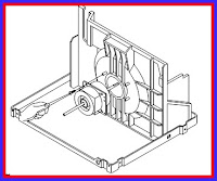
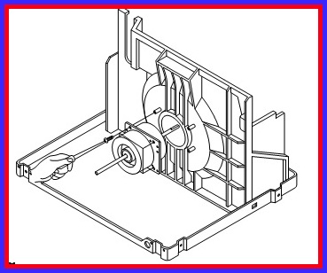
4. AIR GUIDE AND TURBO FAN

1. Remove the front grille.
2. Remove the cabinet.
3. Remove the control box.
4. Remove the 4 screws which fasten the brace.
5. Remove the brace.
6. Remove the 2 screws which fasten the air guide upper.
7. Remove the air guide upper.
8. Remove the 2 screws which fasten the evaporator.
9. Move the evaporator forward and pulling it upward slightly.
10. Pull out the hook of orifice by pushing the tabsand remove it.
11. Remove the clamp with a hand plier which secures the turbo fan.
12. Remove the turbo fan.
13. Remove the 2 screws which fasten the air guide from the base pan.
14. Move the air guide backward, and pull out from the base pan.(Move the air giude lower carefully.)
15. Re-install
the components by referring to the removal procedure, above.

5. FAN
1. Remove the cabinet.
2. Remove the brace.
3. Remove the 5 screws which fasten the condenser.
4. Move the condenser to the left carefully.
5. Remove the clamp which secures the fan.
6. Remove the fan.
7. Re-install by referring to the removal procedure.
1. Remove the cabinet.
2. Remove the brace.
3. Remove the 5 screws which fasten the condenser.
4. Move the condenser to the left carefully.
5. Remove the clamp which secures the fan.
6. Remove the fan.
7. Re-install by referring to the removal procedure.

6. SHROUD
1. Remove the fan.
2. Remove the shroud.
3. Re-install the components by referring to the removal procedure, above.
1. Remove the fan.
2. Remove the shroud.
3. Re-install the components by referring to the removal procedure, above.

Electrical Parts
1. OVERLOAD PROTECTOR
1. Remove the cabinet.
2. Remove the nut which fastens the terminal cover.
3. Remove the terminal cover.
4. Remove all the leads from the overload protector.
5. Remove the overload protector.
6. Re-install the components by referring to the removal procedure, above.
1. Remove the cabinet.
2. Remove the nut which fastens the terminal cover.
3. Remove the terminal cover.
4. Remove all the leads from the overload protector.
5. Remove the overload protector.
6. Re-install the components by referring to the removal procedure, above.

2. COMPRESSOR
1. Remove the cabinet.
2. Discharge the refrigerant system using a FreonTM Recovery System.
If there is no valve to attach the recovery system, install one (such as a WATCO A-1) before venting the FreonTM. Leave the valve in place after servicing the system.
3. Remove the overload protector.
4. After purging the unit completely, unbraze the suction and discharge tubes at the compressor connections.
5. Remove the 3 nuts and the 3 washers which fasten the compressor.
6. Remove the compressor.
7. Re-install the components by referring to the removal procedure, above.

3. CAPACITOR
1. Remove the control box.
2. Open the top cover from the control box.3. Pull out the capacitor from the control box.
4. Disconnect all the leads of capacitor terminals.
5. Re-install the components by referring to the removal procedure, above.
1. Remove the control box.
2. Open the top cover from the control box.3. Pull out the capacitor from the control box.
4. Disconnect all the leads of capacitor terminals.
5. Re-install the components by referring to the removal procedure, above.

4. POWER CORD
1. Remove the control box.
2. Open the top cover from the control box.
3. Disconnect the front panel from the control box.
4. Disconnect two leads from the capacitor and relay.
5. Pull out the power cord.
6. Re-install the component by referring to the above removal procedure, above.
(Use only one ground-marked hole for ground connection.)
7. If the supply cord of this appliance is damaged, it
must be replaced by the special cord.
(The special cord means the cord which has the same specification marked on the supply cord attached at the unit.)


5. MOTOR
1. Remove the cabinet.
2. Remove the turbo fan.
3. Remove the fan.
4. Remove the 4 screws which fasten the motor from the air guide.
5. Remove the motor.
6. Re-install the components by referring to the removal procedure, above.
1. Remove the cabinet.
2. Remove the turbo fan.
3. Remove the fan.
4. Remove the 4 screws which fasten the motor from the air guide.
5. Remove the motor.
6. Re-install the components by referring to the removal procedure, above.
A brief description of the important components
and their function in what is called the refrigeration system. This will help to understand the refrigeration cycle and the flow
of the refrigerant in the cooling cycle.

CIRCUIT DIAGRAM

CLICK ON THE IMAGES TO ZOOM IN